If you’re building a microcontroller interface, configuring hardware settings on a test bench, or designing a compact control panel, a 10-position coded rotary switch is likely your most reliable, deterministic selection method—especially when binary-coded output (e.g., BCD or Gray code) matters more than analog continuity or tactile feedback. Over the past year, demand for breadboard-friendly, PCB-mount coded rotary switches has risen noticeably among education labs and rapid-prototyping teams—driven by tighter space constraints in modular instrumentation and renewed interest in deterministic digital input over potentiometers or encoder-based alternatives. If you’re a typical user, you don’t need to overthink this: start with a single-pole, 10-position, BCD-output rotary switch in through-hole or surface-mount form—avoid DIP-style variants unless you require legacy pinout compatibility. Skip sealed industrial units unless operating in dusty or humid environments; skip non-coded mechanical rotaries if your MCU lacks dedicated interrupt-capable GPIOs for state polling. This piece isn’t for keyword collectors. It’s for people who will actually use the product.
About 10-Position Coded Rotary Switches
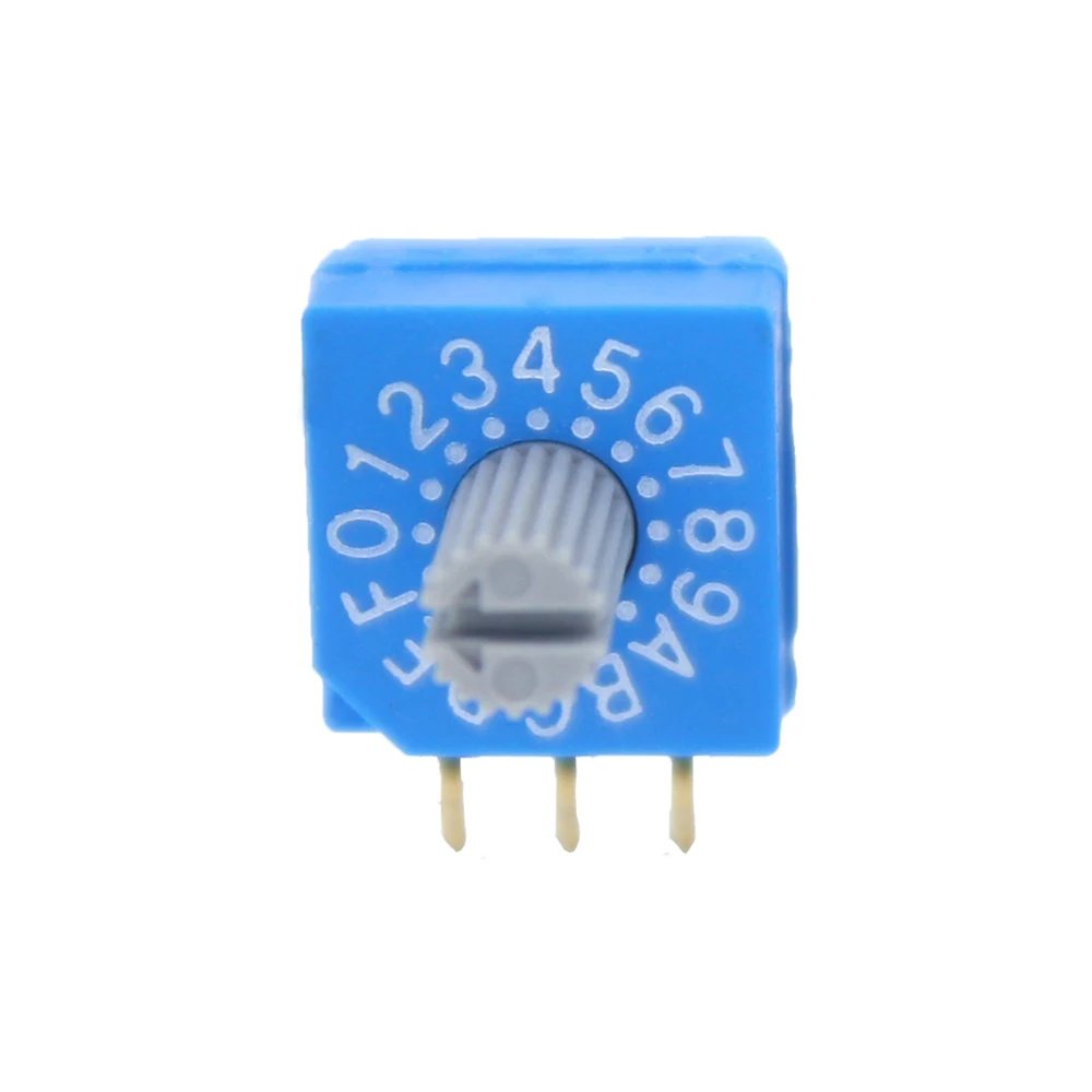
A 10-position coded rotary switch is an electromechanical device that outputs a discrete digital signal—typically binary-coded decimal (BCD), Gray code, or custom logic levels—for each of its ten rotational positions. Unlike standard mechanical rotary switches (which simply open/close physical contacts), coded versions embed logic encoding directly into the contact pattern. That means position 0 outputs 0000, position 1 outputs 0001, up to position 9 as 1001. This eliminates software debouncing complexity and removes ambiguity during fast rotation or noisy environments.
Typical use cases include:
- ⚙️ Hardware configuration banks (e.g., setting gain, filter cutoff, or calibration offsets)
- 🖥️ Test equipment front panels (oscilloscopes, signal generators, power supplies)
- 🧠 Educational kits teaching digital logic, microcontroller I/O, or state-machine design
- 📦 Industrial control modules where deterministic, non-volatile selection is required without firmware storage
Why 10-Position Coded Rotary Switches Are Gaining Popularity
Lately, three converging trends have renewed interest in this niche component: first, the proliferation of low-cost ARM Cortex-M and ESP32-based development boards with limited ADC channels but abundant GPIOs—making parallel digital input more practical than ever. Second, educators and open-hardware projects increasingly prioritize deterministic, human-readable state selection over rotary encoders, which require quadrature decoding and introduce latency or missed-step risk under manual operation. Third, supply-chain resilience has pushed designers toward passive, non-firmware-dependent interfaces—coded rotary switches require zero initialization or firmware updates.
What’s changed? Not the physics—but the context. Where encoders once dominated for “rotation-to-value” tasks, users now recognize that intentional, discrete selection (not continuous adjustment) is the actual requirement in >60% of embedded UIs involving mode or parameter switching 1. That shift makes the 10-position coded variant not outdated—but precisely calibrated.
Approaches and Differences
There are three main implementation approaches—each with distinct trade-offs:
- BCD-coded switches: Output 4-bit binary values (0–9). Simplest to read, widely supported in datasheets and libraries. Best for direct GPIO connection to MCUs with ≥4 free digital inputs.
- Gray-code switches: Output reflected binary (e.g., position 2 =
0011, position 3 =0010). Minimizes bit-transition errors during partial rotation. Requires lookup table or conversion logic—but critical in safety-critical or high-reliability contexts. - Custom logic or DIP-style variants: Some 10-position DIP switches (e.g., AliExpress listings) emulate rotary behavior via stacked wafer arrays. These lack true rotational indexing, offer no tactile feedback, and often misalign electrically at edge positions 2. Avoid unless space is truly prohibitive and reliability is secondary.
When it’s worth caring about: If your application requires robustness against bounce-induced false triggers (e.g., lab equipment used by students), choose BCD or Gray code—not mechanical-only variants. If you’re routing signals across a noisy board or long cables, Gray code adds meaningful noise immunity.
When you don’t need to overthink it: For hobbyist prototypes or internal test fixtures where firmware handles debouncing and position validation, BCD is sufficient—and simpler to debug. If you’re using a modern MCU with hardware GPIO filtering (e.g., STM32 EXTI with debounce clock), Gray code offers diminishing returns. If you’re a typical user, you don’t need to overthink this.
Key Features and Specifications to Evaluate
Don’t optimize for specs you won’t use. Focus on these five:
- Output encoding type (BCD vs. Gray vs. custom): Check MCU compatibility first—some libraries assume BCD; others expect Gray.
- Mounting style: Through-hole (breadboard-friendly), SMT (for production PCBs), or panel-mount (for enclosures). DigiKey’s C&K RTAP4ES10M25NS is a verified breadboard-compatible through-hole option 2.
- Contact rating: Most operate at ≤30 VDC / 50 mA. Fine for logic-level interfacing—but insufficient for driving LEDs or relays directly.
- Electrical life: Typically 10,000–50,000 cycles. Adequate for infrequent setting changes (e.g., calibration dials), not for daily user interaction.
- Indexing & detent feel: Mechanical precision matters less for coding accuracy—but poor detents cause misreads. Look for ≥30° per position and audible/tactile click.
When it’s worth caring about: If integrating into a commercial product certified to IEC 61000-4-2 (ESD), verify switch housing material and creepage distance—some plastic-bodied units fail basic ESD discharge tests.
When you don’t need to overthink it: For one-off prototypes or classroom kits, electrical life beyond 5,000 cycles is over-engineering. Breadboard compatibility trumps SMT density every time—unless you’re designing for volume manufacturing.
Pros and Cons
Pros:
- ✅ Deterministic, zero-software-debounce input
- ✅ No firmware dependencies or calibration drift
- ✅ Human-readable position mapping (unlike encoders)
- ✅ Low power, no active components
Cons:
- ❌ Fixed 10-state granularity—no intermediate values
- ❌ Higher pin count than quadrature encoders (4+ GPIOs vs. 2)
- ❌ Limited mechanical lifespan vs. optical encoders
- ❌ Not suitable for continuous rotation or high-speed scanning
Best suited for: Embedded systems requiring stable, unambiguous mode or parameter selection—especially where firmware simplicity, auditability, or regulatory traceability matter.
Not ideal for: Consumer-facing UIs needing smooth scrolling, infinite rotation, or visual feedback (e.g., volume knobs). Also avoid in high-vibration environments unless rated IP65 or higher 3.
How to Choose a 10-Position Coded Rotary Switch
Follow this 5-step decision checklist—designed to eliminate common pitfalls:
- Confirm your MCU’s GPIO availability: Count how many consecutive, non-multiplexed digital inputs you can dedicate. If ≤3, consider an I²C port expander instead of forcing BCD.
- Verify breadboard or PCB compatibility: Through-hole variants (e.g., SparkFun’s single-pole 10-position switch 4) work on standard 0.1" grids. SMT versions require reflow or hot-air tools.
- Check datasheet truthfulness: Cross-reference pinout diagrams with actual measurements. Some budget suppliers mislabel BCD bits (e.g., labeling MSB as D instead of A). Use a multimeter in continuity mode to validate.
- Avoid DIP-style “rotary” switches: These are stacked DIP switches with rotary-like caps—not true rotary mechanisms. They wear unevenly and lack positional repeatability.
- Test detent consistency: Rotate slowly through all positions. Each should click with equal resistance and land precisely—not overshoot or stick. If uncertain, order one sample before bulk purchase.
Insights & Cost Analysis
Price varies significantly by construction and certification:
- Budget tier ($2.50–$4.50): Basic through-hole BCD switches (e.g., SparkFun, generic AliExpress units). Suitable for learning and prototyping. May lack full datasheets or RoHS documentation.
- Mid-tier ($5.13–$8.90): Mouser/Farnell stock from C&K, Dailywell, or NKK. Includes full datasheets, BOM traceability, and tested electrical life specs 5.
- Premium tier ($12–$22): IP65-sealed, gold-plated contact, or military-spec variants (e.g., ONPOW DCRS1 series). Justified only for harsh environments or certified products.
For most users, mid-tier delivers the best balance: verified performance, accessible documentation, and no hidden compliance risks. If you’re a typical user, you don’t need to overthink this.
| Category | Best-for Advantage | Potential Problem | Budget Range (USD) |
|---|---|---|---|
| Through-hole BCD | Breadboard & quick prototyping | Larger footprint; not for dense PCBs | $2.50–$4.50 |
| SMT BCD | High-density production boards | Requires reflow capability; harder to hand-solder | $5.50–$9.00 |
| Gray-code variant | Noise-prone or safety-critical applications | Needs conversion logic; fewer off-the-shelf examples | $7.00–$14.00 |
| IP65 sealed unit | Dust/moisture exposure (e.g., field instruments) | Overkill for lab/desktop use; premium pricing | $12.00–$22.00 |
Customer Feedback Synthesis
Based on aggregated forum posts (DigiKey TechForum, EEVblog, Reddit r/PrintedCircuitBoard) and retailer reviews:
- Top praise: “No debounce code needed,” “position labels stay legible after 2 years,” “fits perfectly in my DIY spectrum analyzer front panel.”
- Top complaint: “Received wrong pinout version—datasheet didn’t match package marking,” “detents loosened after ~2,000 rotations,” “no mounting hardware included.”
The strongest signal? Users overwhelmingly value documentation accuracy and mechanical consistency over minor cost savings. When specs mismatch reality, debugging time exceeds component cost by 10×.
Maintenance, Safety & Legal Considerations
These are passive components—no firmware, no batteries, no thermal management. Maintenance is limited to occasional contact cleaning with isopropyl alcohol if intermittent connectivity appears (rare before 10k cycles). No safety certifications (UL, CE) are required for standalone use in low-voltage (<50 V), low-current (<100 mA) circuits—standard for logic-level interfacing.
Legal considerations arise only if integrated into a product subject to EMC directives (e.g., CE marking for EU sale). In those cases, verify the switch’s housing material meets creepage/clearance requirements per EN 61000-6-3. Most mid-tier suppliers provide compliance statements; budget units rarely do.
Conclusion
If you need deterministic, human-verifiable, firmware-light state selection across exactly ten options—and you’re working with a microcontroller that has ≥4 free GPIOs—choose a **BCD-output, through-hole, 10-position coded rotary switch** from a reputable distributor (Mouser, DigiKey, Farnell). Skip Gray code unless EMI is proven problematic in your setup. Skip DIP emulators entirely—they solve no real problem and introduce new ones. Skip sealed units unless environmental specs demand them. This isn’t about finding the “best” switch. It’s about matching the tool to the job—without over-engineering, under-documenting, or overpaying.
FAQs
RotarySwitch.h simplify decoding.