Free Amplifier Circuit

Overview
Product sourcing insights & recommendations
The phrase "free amplifier circuit" primarily refers to the widespread availability of open-source circuit designs and schematics used by DIY hobbyists and engineers for building audio amplification systems WonderfulpcbAllpcb. The market for these circuits and their related board modules is experiencing a shift toward high-efficiency Class-D technology and modular DIY kits YahooSphericalinsights.
Market Trends & Insights (2026)
* Dominance of Class-D: Class-D amplifiers now command nearly 50% of the audio market due to their 90%+ energy efficiency and compact size, making them essential for portable and smart home devices SphericalinsightsMordorintelligence.
* Gallium Nitride (GaN) Integration: GaN technology is a high-growth sector (7.17% CAGR), enabling heatsink-free high-power modules (500W+) that switch faster and run cooler than traditional silicon SphericalinsightsEmbeddedcomputing.
* AI-Enhanced Audio: Emerging trends for 2026 include AI-based acoustic profiling, where amplifiers use real-time processing to tune sound according to the environment SphericalinsightsMordorintelligence.
* DIY & Prototyping Growth: The popularity of "free" circuits is fueled by platforms like LTspice (circuit simulation) and Raspberry Pi HATs, which allow for rapid prototyping of Hi-Fi systems AllaboutcircuitsSphericalinsights.
Product Opportunities
I have identified several high-potential product categories for sourcing and development:
* 2.1 Channel Bluetooth Boards: Versatile modules (e.g., 50W+50W+100W) priced around $10–$14, popular for custom home theater and karaoke builds AlibabaAlibaba.
* High-Power Hi-Fi DIY Kits: Discrete component and IC-based kits (TPA3255, TAS5630) that support power levels up to 1200W for professional audio applications AlibabaAlibaba.
* GaN Power Modules: Advanced boards designed for reduced SWaP (Size, Weight, and Power) requirements, ideal for aerospace, defense, and premium pro-audio sectors GlobalspecEmbeddedcomputing.
Diy Bluetooth Amplifier Board 100w 2.1 Channel
Products · 3 lists
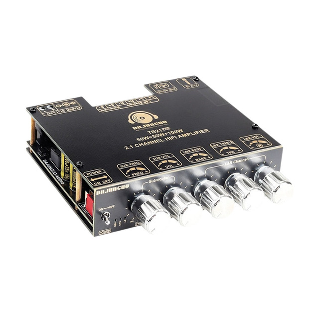
Audio Amplifier Board ZK-TB21 2.1CH 50W TB21 PRO 2.1 Channel 5.2 Stereo Amplifier Board 50W+50W+100W7827
 Shenzhen Maojiexin Electronics Co., Ltd.verified🇨🇳CN4 yrs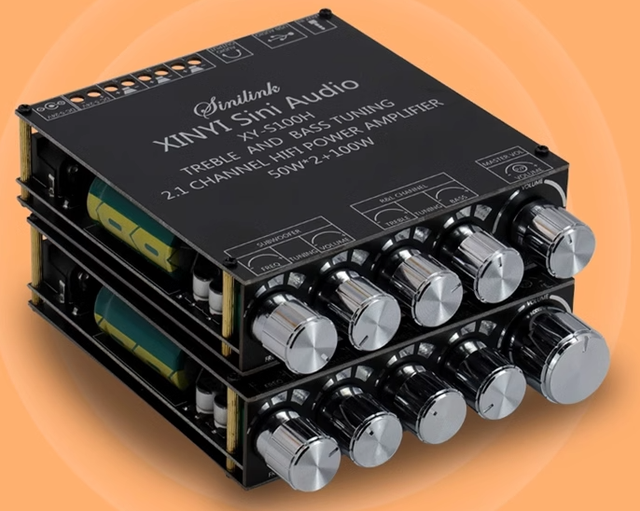
XY-S100L/H 50W * 2+100W2.1 Channel Audio Amplifier Board Module for High and Low Frequency Adjustment
 Shenzhen Xinliwei Electronics Technology Co., Ltd🇨🇳CN6 yrs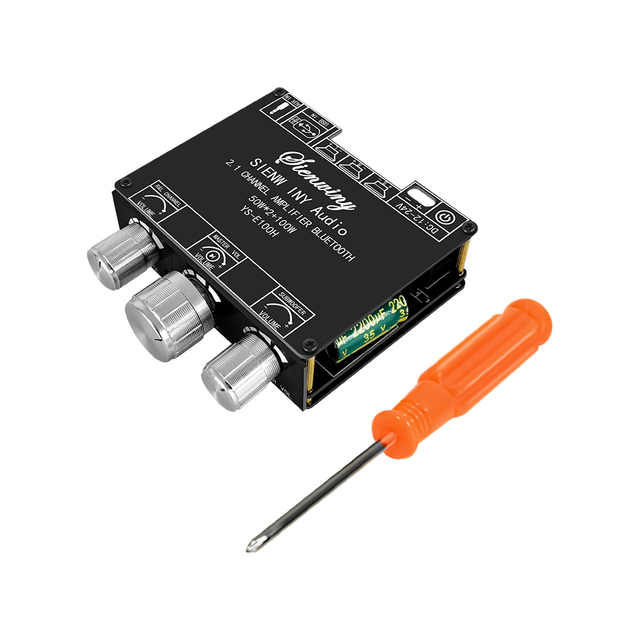
XY-E100H HiFi 50W*2+100W Metal Shell Power Amplifier Board 2.1 Channel for 5.1 Subwoofer Module Home Theater AUX
 Shenzhen Youdianduo Technology Co., Ltd.🇨🇳CN4 yrs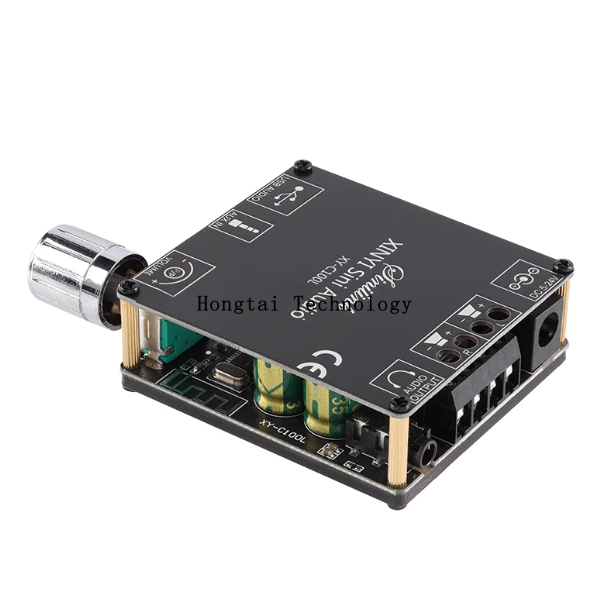
XY-C100L 2*100W Stereo Wireless Bluetooth Digital Amplifier Board Dual Channel 360 Degree Infinitely Tunable module
 Shenzhen Hongtai Shengye Technology Co., Ltd.🇨🇳CN2 yrs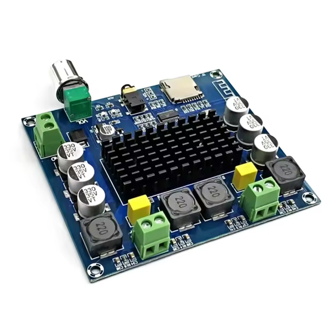
TDA7498 Bluetooth 5.0 Digital Amplifier Board XH-A105 2*100W High Power Dual Channel Audio Module
 Shenzhen Youxinbang Technology Co., Ltd.🇨🇳CN2 yrs
Related Searches
Explore more sourcing topics & related categories
Sources & References
29 sources cited · Verified industry data & reports
How to Design and Build a Simple Amplifier Circuit
www.wonderfulpcb.com
Designing an amplifier circuit is a fun way to learn electronics. First, understand how signals get louder or stronger. Then, pick parts like resistors, capacitors, and a transistor. A basic amplifier boosts sound, which is great for beginners. While building, you’ll see how to connect parts to make it work. Picking the right parts, like resistors and capacitors, helps the circuit work well. These parts also keep the sound clean and strong. Studies show that following certain rules improves amplifiers. The table below lists important findings and how they help design better amplifiers: By using these ideas, you can make an amplifier that works well and meets standards. Before building, you need a clear PCB Design plan. A circuit diagram shows how parts connect. Symbols represent parts like transistors, resistors, and capacitors. Tip: Test your circuit online before building it. This saves time and parts by showing if it works. Learning about signal amplification and making good diagrams are key steps. These steps help you design a reliable amplifier.
Half-Hour Project: Building a Simple Audio Amplifier - element14 ...
community.element14.com
The amplifier performed reasonably OK (by that I mean adequate for speech, it's not hi-fi!), considering how simple the circuit was. This blog post discusses the design. I think it is a nice beginner project because it can be assembled within half an hour. I prepared some documentation for this project because it is intended to be used for soldering practice. This is from TI's Designing with TTL Integrated Circuits · They are talking about this circuit for a typical gate · It was a lighthearted way for the engineers to distinguish active outputs from passive o/c ones. The terminology for output stages is all quite woolly. To me 'push-pull' simply means actively sourcing or sinking current to/from the load. Cheap headphone amplifier integrated with DAC Goal + good quality headphone amplifeier; + good quality DAC; + integrated device for cost reduction (one power supplly and one housing); + headphone amp... ... Introduction Radio Circuit Amplifier Circuit Power Entry Circuit Board Wiring Diagram Soldering Enclosure Components and Parts List Potentiometers ... Looking at the circuit from right-to-left, the two totem-pole transistors Q2 and Q3 operate in a push-pull arrangement, to drive the output high or low; these two transistors provide the current gain for the amplifier.
A list of Simple audio circuits and amplifiers for DIY(Do it Yourself)
circuitstoday.com
2. 100 Watt Audio amplifier based on TDA7294 – This is an IC based (TDA7294) amplifier circuit which can easily deliver 100 Watts RMS output into an 8 ohms speaker. The TDA7294 has low noise, low distortion, good ripple rejection and can be operated from a wide range of supply voltages. It’s an IC specifically designed for Hi Fi audio applications. 6. 3 Channel audio splitter circuit – This is a simple 3 channel audio splitter circuit designed with op amp NE5532 from Fairchild semiconductors.NE5532 is a dual internally compensated low noise opamp with high small signal and power bandwidth, making it well suited for high quality audio applications. 7. 2×60 Watts audio amplifier – This is a high quality audio amplifier designed using LM4780 IC, which is capable of delivering 60 watts RMS power per channel into 8 0hms speakers. This circuit is designed using PCM2702 which is an integrated 16 bit digital to analog converter that has two digital to analog output channels.This IC also has a number of useful features like on-chip clock generator, digital attenuator, play back flag, suspend flag, zero flag, mute function etc. This article is a compilation of the simple and popular audio circuits we have published over years in CircuitsToday. This list involves a collection of simple amplifier circuits that you can try at home and some other audio related circuits with specific applications.
Discrete Component Audio Amplifiers: Building a Classic Design
www.allpcb.com
For instance, you might choose a transistor with a specific gain (hFE) value to match your design needs. Durability: Discrete components can often handle higher voltages and currents compared to some ICs, making them suitable for high-power audio applications. When it comes to discrete audio amps, the Class A amplifier is a classic choice due to its simplicity and excellent sound fidelity. In a Class A amplifier circuit, the output transistors conduct the full input signal cycle, meaning they are always "on" and drawing current. Unlike amplifiers using integrated circuits, a discrete audio amp is constructed using individual components like transistors, resistors, and capacitors. This classic design, often centered around a Class A amplifier circuit, offers superior sound quality and a deep understanding of audio electronics. Whether you're a hobbyist or an engineer, this blog post will cover the essentials of discrete component audio amplifiers, why Class A designs are a popular choice, and step-by-step instructions to create your own amplifier circuit. A discrete component audio amplifier is a type of amplifier built using individual electronic parts rather than pre-made integrated circuits (ICs). These parts include transistors (like BJTs or MOSFETs), resistors, capacitors, and sometimes diodes, all wired together to amplify an audio signal. This approach contrasts with modern designs that rely on ICs, which pack entire amplifier circuits into a single chip for convenience and cost savings.
Simple amplifier circuit | diyAudio
www.diyaudio.com
I could test 'em - not design them. Be encouraged to explore your little circuit, particularly in the area of refinement. Take it as far as you can in only for your own learning and experience, before jumping into "oh this other one is so much better". There's a 1000 ways to fry the audio amplification-egg and you can get overwhelmed easily swimming through the myriad of choices. If we ignore that undesirable DC speaker current, the bias resistor should be roughly the load resistance times the transistor gain, ie about 100 x 6 = 600 Ohms. This is a very crude circuit for educational purposes, but it is not good enough for actual use long term. You should search these web pages for simple "headphone amplifiers" which are also very simple but good enough to be actually useful. But it is probably the very first transistor amplifier ever made, it has a place in history! Click to expand... It'll be a photo finish with the emitter and collector pins accidentally swapped, assuming there was a distinction in the early days. ... Make it this way: View attachment 1239559 View attachment 1239565 This will work. Put BD139 on some heatsink. P.S.: I sincerely hope your post #1 is a good joke 🙂. Click to expand... If I don't have AC voltage source, how will the circuit change or there is sth to replace? You will make no changes in the circuit. You may use your 2SD718, it will work same as my 2SC5200. ... Look, you should start to study the absolute basics, basics of reading schematics. I have already explained that the speaker is connected instead of R3, at the same place. R3 = speaker. You also have a photo. You said you are a student of electronics, but I do not think so. P.S.: I have connected this "amplifier" to the small 2-way speaker, and the sound is absolutely normal, as long as we stay inside its power capabilities.
Audio Amplifier Projects and Design Tutorials
www.circuitbasics.com
See how each part of the circuit works, how to calculate the best component values, and how to layout the PCB and wire your amplifier for great sound. ... This tutorial will show you how to connect a 3.5 mm audio jack from an old pair of headphones to the audio input of your DIY audio projects. ... Design and build a 25 Watt stereo amplifier with the TDA2050 – change the gain, set the bandwidth, layout the PCB, and wire it in a chassis. Designed around the LM4562 op-amp, this Hi-Fi stereo preamplifier features six switchable RCA inputs, volume, tone and balance controls, and much more! ... Build an audio amplifier with excellent sound quality using the LM1875 audio amplifier chip. Step by step instructions and schematics included. ... Learn how operational amplifiers work, how to build an op-amp circuit, and some important parameters to consider when choosing an op-amp. Need a guide in designing your own transistor amplifier? Learn here the basics of gain, calculating gain, biasing, among others! ... Learn how to build non-linear op-amp circuits like a comparator, rectifier, peak detector, and constant volume amplifier. Learn how to build eight different op-amp circuits, including an inverting and non-inverting amplifier, voltage follower, differential amplifier, integrator, differentiator, and summing amplifier.