Pwm Op Amp

Overview
Product sourcing insights & recommendations
I have analyzed the PWM op amp market and product landscape for 2026. The shift toward high-efficiency power management in EVs, industrial automation, and consumer IoT is driving a robust CAGR of ~7% for integrated operational amplifiers. While traditional linear designs are mature, PWM-based architectures are gaining significant traction due to their 80–95% efficiency and superior thermal performance.
The attached report provides a detailed breakdown of:
- Technical Principles: Averaging principles and closed-loop feedback in PWM circuits.
- Top Product Picks: From precision ICs like Texas Instruments' OPA series to high-power modules like the Apex PA164.
- Market Drivers: Analysis of the impact of the EV transition and Industry 4.0 on demand.
- Strategic Recommendations: Best entry points for automotive and industrial designers.
Based on these trends, you may want to:
High Power Pwm Amplifier Module
Products · 3 lists
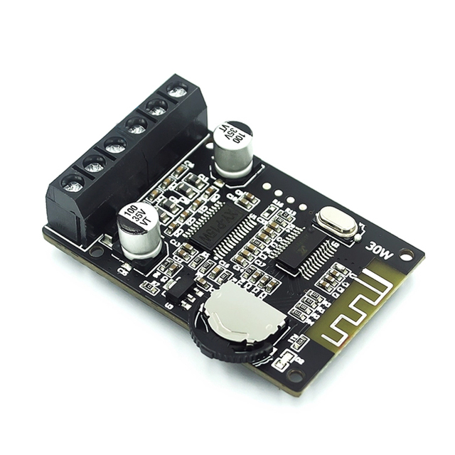
Stereo Power Amplifier Board 12V/24V High-power Digital Power Amplifier Module XY-P15W
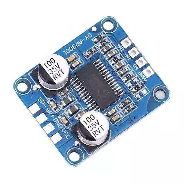
Factory Direct Sales 10W/20W/30W High Power Amplifier Module Class D Digital Amplifier Board 12V/24V Power Supply DY-AP3001
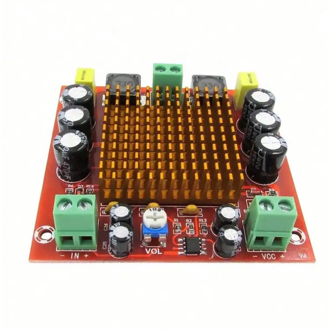
High power 150W professional power amplifier 12-26V DC 12V 24V audio module
 Shenzhen Ali Xin Chao Technology Co., Ltd.🇨🇳CN1 yr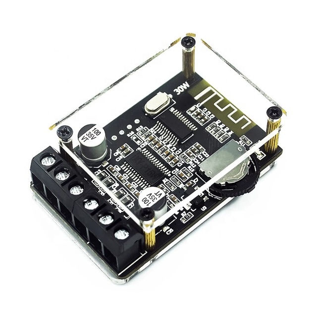
XY-P15W 10W 15W 20W Stereo Power Amplifier Board 12V 24V High Digital Power Amplifier Module
 Shenzhen Binyueda Electronics Co., Ltd.🇨🇳CN6 yrs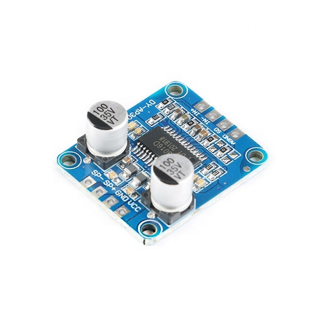
10W / 20W / 30W High Power Amplifier Module Class D Digital Power Amplifier Board 12V / 24V Power Supply DY-AP3001
 Shenzhen Alisi Electronic Technology Co., Ltd.🇨🇳CN8 yrs
Deep Dive · Full Report
Full Market Report
1 document · Live-fetched from source
Related Searches
Explore more sourcing topics & related categories
Sources & References
19 sources cited · Verified industry data & reports
Activity: Pulse Width Modulation [Analog Devices Wiki]
wiki.analog.com
Figure 8. PWM with Astable Multivibrator · The circuit shows an astable multivibrator using a single operational amplifier. The functionality is easy to understand while considering the functional principle of a Schmitt trigger (comparator circuit with hysteresis studied in Activity: Op Amp as Comparator): The input of the Schmitt trigger, which is identical to the inverting input of the operational amplifier, is connected to the output of the circuit via a resistor-capacitor network. Following the description of the PWM principle, we use the negative input of the operational amplifier for carrier, while the positive input for the modulation signal. By varying a digital signal off and on at a fast-enough rate, and with a certain duty cycle, the output will appear to behave like a constant voltage analog signal when providing power to devices that respond much slower than the PWM frequency, such as audio speakers, electric motors, and solenoid actuators. ADALM2000 Active Learning Module Solder-less breadboard, and jumper wire kit 1 OP97 operational amplifier 1 1kΩ resistor 1 10kΩ potentiometer Supply the op amp with +5V from the power supply. Configure the scope so that the input signal is displayed on channel 1 and the output signal is displayed on channel 2 . In the figure there are presented the two signal generator channels containing the two input signals (orange - carrier signal, purple - modulation signal). Figure 3. Input Signals · A plot of the output signal on channel 2 of the scope is presented in Figure 4. Figure 4. PWM output
Pulse-Width Modulator Operates at Various Levels of Frequency and ...
www.analog.com
Build a general-purpose pulse-width modulator using three op amps from a quad-op-amp device. The many applications for pulse-width modulation (PWM) include voltage regulation, power-level control, and fan-speed control. A PWM circuit for such applications (Figure 1) can be implemented with three op amps from a single quad-op-amp chip. Figure 2. The Figure 1 circuit produces these PWM and triangular-wave outputs. The ratio of R2 and R1 affects the operating frequency and the amplitude of the triangular wave. Given that VTH is the triangular wave's maximum voltage and VTL is its minimum voltage, the amplitude swing is: The triangular wave's peak-to-peak voltage (the difference in its maximum and minimum voltages) is centered at the VCC/2 bias voltage generated by R3 and R4. The circuit configuration shown allows the PWM to operate on a single supply. The use of op amps allows a wide variety of applications. Low-power op amps can be used in a low-power system, for example, and high-frequency op amps can be used for a high-frequency PWM.
PWM Pulse Signal Generator Circuit Using LM358 Op-Amp ...
www.circuits-diy.com
The RC square wave output of the Op-Amp IC serves as the control signal to the gate terminal of the IRF540 power MOSFET. The drain output of which is connected to a DC motor, allowing it to be driven at a high current. PWM signal is used for applications such as controlling DC motors, valves, pumps, hydraulics, and other mechanical parts. 7) Connect a DC motor or an LED to the circuit output, in order to adjust the duty cycle of the PWM signal. Now, Power up & test the circuit. The working of the circuit is as follows: Here we are using an LM358 Op-Amp in A-stable multi-vibrator mode to produce a free-running square wave signal. Computer Motherboards require PWM Signals that control the heat generated on the board. ... 2n3904 555 timer Adjustable Regulator arduino arduino uno audio amplifier battery charger bc547 bridge rectifier cd4017 cmos counter darlington transisor EEPROM EPROM Fast Recovery Diode fm transmitter high voltage jfet ldo LDR LED led flasher light lm317 lm358 lm741 N Channel MOSFET NE555 npn transistor operational amplifier pcb pnp transistor power amplifier power MOSFET power supply power transistor printed circuit board relay switch temperature sensor triac Ultrafast Diode voltage regulator zener diode Basically, in pulse width modulation, the energy is divided between a series of pulses, rather than a continuously varying analog signal. A PWM Pulse Signal Generator implements the PWM function, using which you can control devices such as DC motors. So, In today’s tutorial, we are going to design a simple PWM Pulse Signal Generator Circuit Using LM358 Op-Amp IC.
Analog Lab - PWM Power Controller | Analog IC Projects | Electronics ...
www.allaboutcircuits.com
The PWM signal generator of Figure 1 uses a 555 timer to generate a sawtooth voltage waveform across a capacitor. It then compares that signal against a variable reference voltage using open-loop operational amplifiers (op amps) operating as comparators. Otherwise, it is possible (though unlikely) that one op amp could turn on before the other, and damage results from the two outputs short-circuiting each other (one driving high and the other driving low simultaneously). The three diodes in series connecting the op amps’ outputs to the transistor’s base are there to drop voltage and ensure the transistor falls into cutoff when the op amp outputs go low. Since the 1458 op amp cannot swing its output voltage all the way down to ground potential but only to within about 2 V of ground. Adding three silicon diodes in series drops approximately 2.1 V (0.7 V times 3) to ensure there is a minimal voltage at the transistor’s base when the op amp outputs go low. ... Step 1: Build the circuit of Figure 1 and represent it by the breadboard implementation shown in Figure 2. Step 2: If you have an oscilloscope, view the capacitor voltage, potentiometer voltage, and op amp output waveforms to see how they relate to one another and to the load power.
operational amplifier - PWM with op-amp, but can't figure out ...
electronics.stackexchange.com
Bring the best of human thought and AI automation together at your work. Explore Stack Internal ... I want to make a way to control the high time with a control voltage, instead of using a variable resistor. For this I have found this diagram with an op-amp, and I have tested it in Multisim (a simulation tool for electronics.) It seems to do some kind of PWM. Only if there's a difference of more than 20% is it worth discussing what went wrong. I am not that well versed in op amp circuits Then read: Opamps for Everyone: web.mit.edu/6.101/www/reference/op_amps_everyone.pdf also, read the datasheet of the MAX998, is it an opamp or something else? \$\begingroup\$ I would simulate this with a voltage controlled voltage source, gain = 10000, min. output voltage = 0 V and max. output voltage = 5 V. That way I'm completely independent of any weird behavior of the IC's model I do not know of. I can always put in a "real" opamp/comparator later to see what changes. But yeah, that's just me and how I work. So we may conclude that the maximum input voltage for reliable operation is 2.6V using the MAX998. This will limit the maximum reliable "on" duty cycle.
AN30 AN30U 1 AN30 PWM Basics 1.0 INTRODUCTION
apexanalog.com
is important to understand how a PWM system behaves open · loop. PWM amplifiers are affected by a variety of influences · that rarely come into the picture in a linear design, or they are · present in a much more subtle way than with PWMs. Hope- fully, this discussion impresses the importance of closing the ... PWM amplifier. This can eliminate all of the effects of the · sources mentioned above - and others that have not been · mentioned. Application note 41 discusses several methods for section on designing with PWM amplifiers is NOT intended for · optional reading. less protected PWM amplifiers. The final section examines ... Figure 2 illustrates the most basic PWM operation. two components for satisfactory operation of the amplifier. Use · at least 10µF per ampere of load current to bypass the lower · frequencies. Some applications appear to require many times