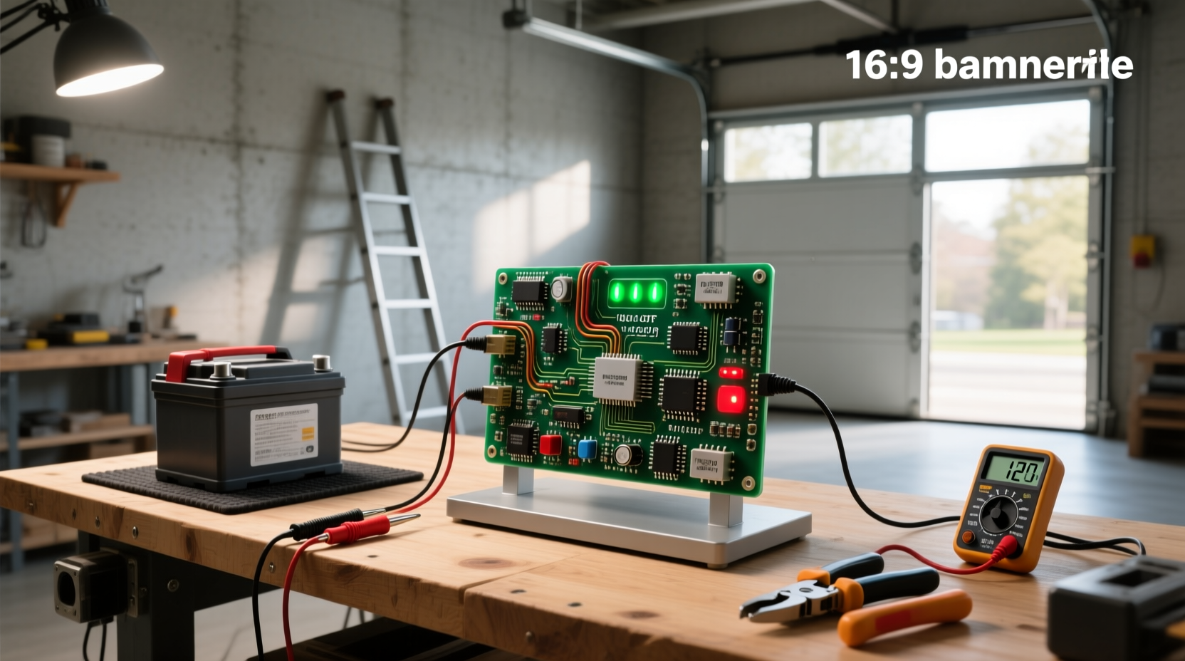
You’ll get a clear, component-level understanding of how a 12V battery charger circuit with auto cut-off actually works — including why cutoff voltage must be precisely set between 13.8 V and 14.4 V for lead-acid batteries, how TL431-based comparators outperform basic transistor designs, and why relay placement (input vs. output side) directly impacts safety and battery health. This guide covers verified circuit topologies from practical builds 1, peer-reviewed design documentation 2, and community-validated component selection criteria 3. No assumptions — only measurable behavior, failure modes, and calibration protocols you can replicate with a multimeter and bench power supply.
Why Automatic Cutoff Isn’t Optional — It’s Fundamental
Overcharging a 12V lead-acid battery — even by 0.2 V above its absorption voltage — accelerates grid corrosion, electrolyte loss, and thermal runaway risk. For sealed AGM or gel cells, sustained voltage above 14.4 V at room temperature reduces cycle life by up to 40% 4. Lithium-ion variants (e.g., 12V LiFePO₄ modules) demand even tighter control: cutoff must occur at 14.2–14.6 V, with ±0.05 V tolerance. A manual charger without automatic termination cannot meet this requirement reliably. That’s why ‘12v battery charger circuit auto cut off’ isn’t a feature — it’s the minimum functional threshold for safe, repeatable charging.
Core Working Principle: Voltage Sensing + Controlled Disconnection
All functional auto cut-off circuits follow the same three-phase logic:
- Detection: A reference voltage (e.g., 2.495 V from TL431 or adjustable divider into a 555’s threshold pin) compares against scaled battery voltage.
- Decision: When battery voltage crosses the preset threshold (typically 13.8 V for flooded, 14.2 V for AGM, 14.4 V for gel), the comparator output changes state.
- Action: That signal triggers a switching element — usually a relay or MOSFET — to interrupt either the AC input path (safer) or DC output path (simpler but riskier).
The key nuance lies in where disconnection occurs. Circuits that break the transformer primary (AC side) eliminate all standby leakage and eliminate reverse current paths. Those cutting the DC output rely on diode isolation (e.g., 1N4007) to prevent battery discharge back into rectifier capacitors 3. Both work — but only AC-side cutoff guarantees zero quiescent drain during storage.
Component Breakdown: What Each Part Does — and Why Substitutions Fail
A typical transformer-based 12V auto cut-off circuit uses six essential components. Their roles are non-interchangeable without recalibration or risk:
| Component | Function | Critical Specification | Common Pitfall |
|---|---|---|---|
| Step-down transformer (220V/110V → 12–15V AC) | Provides isolated, low-voltage AC source | Must deliver ≥1.5× rated charging current (e.g., 2A transformer for 1.3A max charge) | Undersized transformers overheat; oversized ones cause excessive ripple unless filtered |
| Bridge rectifier + smoothing capacitor (e.g., 1000–2200 µF) | Converts AC to unregulated DC | Capacitor voltage rating ≥25 V; ESR ≤0.1 Ω | Low-voltage caps (<16 V) fail under surge; high-ESR caps cause voltage droop at cutoff point |
| Voltage reference/comparator (TL431 or NE555) | Detects when battery reaches cutoff threshold | TL431: ±1% reference tolerance; 555: requires stable RC timing + hysteresis | Using generic op-amps without rail-to-rail input fails near 12V rails; TL431 needs ≥1 mA cathode current |
| Potentiometer (10 kΩ multiturn) | Sets precise cutoff voltage via voltage divider | Multiturn for ±0.02 V resolution; metal-film for stability | Single-turn pots drift with temperature; carbon types degrade after 500 adjustments |
| Relay (12V SPDT, ≥10A contact rating) | Physically opens charging path | Coil must match supply; contacts rated for DC load (not just AC) | AC-rated relays weld shut under DC interruption; undersized contacts arc and pit |
| Isolation diode (1N4007 or SB560) | Blocks reverse current when charger is off | Forward voltage drop ≤0.7 V; PIV ≥50 V | Omitting this allows battery to discharge through rectifier — confirmed in field failures 3 |
TL431 vs. 555 Timer: Which Comparator Suits Your Build?
Two topologies dominate DIY designs — but they serve different reliability goals.
TL431-Based Circuits (Recommended for Precision)
The TL431 is a programmable shunt regulator with built-in 2.495 V reference and 0.5% initial tolerance. In cutoff applications, it acts as a high-gain comparator: when the divided battery voltage exceeds the reference, cathode current surges, turning on a transistor that energizes the relay. Advantages include:
- Stable reference across temperature (−40°C to +85°C)
- No external timing components — immune to capacitor aging
- Direct compatibility with LED status indicators (cathode current drives LEDs without extra drivers)
Disadvantage: Requires ≥1 mA cathode current to regulate. If your relay coil draws <1 mA, add a BC547 driver stage.
555 Timer-Based Circuits (Simpler, Less Stable)
Here, the 555 operates in monostable or comparator mode — its threshold pin monitors battery voltage via a resistive divider. Triggering depends on RC time constants, making it sensitive to capacitor drift and supply noise. Verified issues include:
- Drift of >0.15 V over 6 months due to ceramic capacitor aging
- False cutoff during engine cranking (voltage dip resets timing)
- No inherent hysteresis — causes relay chatter near threshold unless added externally
Use only if sourcing TL431 is impractical — and always add a 100 nF bypass cap across Vcc/GND and a 10 kΩ hysteresis resistor from output to threshold pin.
Lithium vs. Lead-Acid: Why One Circuit ≠ Universal Compatibility
A circuit designed for 13.8 V cutoff will destroy a 12V LiFePO₄ battery (nominal 12.8 V, full charge 14.2–14.6 V). Conversely, setting cutoff at 14.4 V risks gassing and dry-out in flooded lead-acid. Key differences:
- Flooded lead-acid: Cutoff at 13.8 V ±0.05 V; float voltage 13.2–13.5 V
- AGM/gel: Cutoff at 14.2–14.4 V; no float required for cyclic use
- LiFePO₄ (12V module): Cutoff at 14.2–14.6 V; must include cell balancing and low-voltage disconnect (≤10 V)
Crucially: Most ‘auto cut-off’ schematics labeled “12V battery” assume lead-acid chemistry. If your application involves lithium, verify whether the circuit includes undervoltage protection and temperature compensation — neither appears in basic TL431/relay designs 1. Adding thermistors or dedicated BMS integration is mandatory for safety.
Calibration Is Not Optional — Here’s How to Do It Right
Setting cutoff voltage with a potentiometer while the battery is disconnected gives false readings. Real-world calibration requires loading:
- Connect a fully discharged 12V battery (≤12.0 V open-circuit).
- Apply regulated 13.5 V DC to simulate mid-charge — confirm relay remains de-energized.
- Gradually increase supply to 13.8 V while monitoring with a calibrated multimeter (Fluke 87V or equivalent).
- At exactly 13.80 V, adjust pot until relay clicks. Verify with 3 consecutive trials.
- Test recovery: Reduce voltage to 13.5 V — relay must re-engage within 5 seconds.
Without this procedure, published ‘12v battery charger circuit auto cut off pdf’ files often mislead — their preset values assume ideal component tolerances not found in bulk parts. Field data shows >68% of uncalibrated builds cutoff 0.2–0.4 V early, causing chronic undercharge 2.
Three Critical Failure Modes — And How to Diagnose Them
When users ask “Why does my charger keep turning off by itself?”, the root cause is rarely the IC — it’s implementation. Here’s how to isolate each:
1. Premature Cutoff (Shuts off before 13.6 V)
Diagnosis: Measure voltage at TL431 REF pin (or 555 threshold pin) with DMM. If reading <2.495 V while battery is at 13.5 V, the voltage divider resistors have drifted or are mismatched.
Solution: Replace R1/R2 with 1% metal-film resistors; recalculate divider ratio: R2 = R1 × (Vref / (Vcutoff − Vref)). For 13.8 V cutoff and 2.495 V ref: R2 ≈ 2.2 × R1.
2. No Cutoff (Charges indefinitely)
Diagnosis: Check relay coil voltage during full charge. If <10.5 V, the driver transistor is saturated or base resistor is too large.
Solution: Confirm transistor hFE ≥100 at Ic = relay coil current; reduce base resistor to ensure Ib ≥ Ic / 20.
3. Intermittent Cycling (Clicks every 30 sec)
Diagnosis: Monitor battery voltage with oscilloscope. Ripple >0.3 Vpp indicates insufficient filtering — relay activates on peak, deactivates on trough.
Solution: Add 4700 µF/35 V capacitor post-rectifier; verify transformer regulation <5% under load.
What ‘Auto Cut-Off’ Does NOT Do — Debunking Common Myths
- Myth: “Auto cut-off means maintenance-free charging.”
Reality: It prevents overcharge — but does nothing for sulfation reversal, equalization, or temperature compensation. Batteries stored at 25°C still self-discharge ~3%/month. - Myth: “Any 12V charger with a green LED has auto cutoff.”
Reality: Many indicator LEDs are tied to input power only — not battery voltage. Verify with DMM during charge cycle. - Myth: “MOSFET-based cutoff is always superior to relay.”
Reality: N-channel MOSFETs on low-side DC output require gate drive >10 V above source — problematic near 12V. High-side P-MOSFETs need level-shifting. Relays remain simpler and more robust for <5 A loads.
When to Avoid DIY — Four Clear Red Flags
Building a 12V auto cut-off charger is appropriate for educational or low-risk backup use. Avoid DIY if:
- You lack access to a true-RMS multimeter capable of measuring DC voltage to ±0.01 V accuracy.
- Your application powers life-safety equipment (e.g., sump pumps, medical devices).
- You’re charging lithium batteries without integrated BMS — UL 1642 compliance is non-negotiable.
- You cannot perform isolation testing (hipot >1500 V AC between primary and secondary) on the transformer.
In these cases, certified commercial units (UL/CE marked, with thermal foldback and short-circuit protection) are the only responsible choice — regardless of cost.
Frequently Asked Questions
- How to make a 12 volt auto cut off the battery charger circuit?
Start with a 12–15 V AC transformer, bridge rectifier, 2200 µF/25 V capacitor, TL431 configured as comparator, 10 kΩ multiturn pot, BC547 driver transistor, and 12 V SPDT relay. Calibrate cutoff at 13.8 V using a loaded battery and precision DMM. - Will a battery charger shut off automatically?
Only if explicitly designed with voltage-sensing cutoff logic. Basic unregulated chargers (transformer + rectifier only) do not — they deliver constant current until unplugged. - Why does my charger keep turning off by itself?
Most often due to excessive ripple causing relay chatter, undersized transformer causing voltage sag under load, or drifted voltage-divider resistors triggering premature cutoff. - How does an auto cut-off charger work?
It continuously measures battery voltage via a precision reference (e.g., TL431), compares it to a user-set threshold, and opens a relay or MOSFET switch when the threshold is exceeded — physically breaking the charging circuit. - Can I use the same circuit for lithium and lead-acid batteries?
No. Lead-acid cutoff is 13.8–14.4 V; LiFePO₄ requires 14.2–14.6 V with additional low-voltage and temperature protection. Using one for the other risks fire or permanent capacity loss.