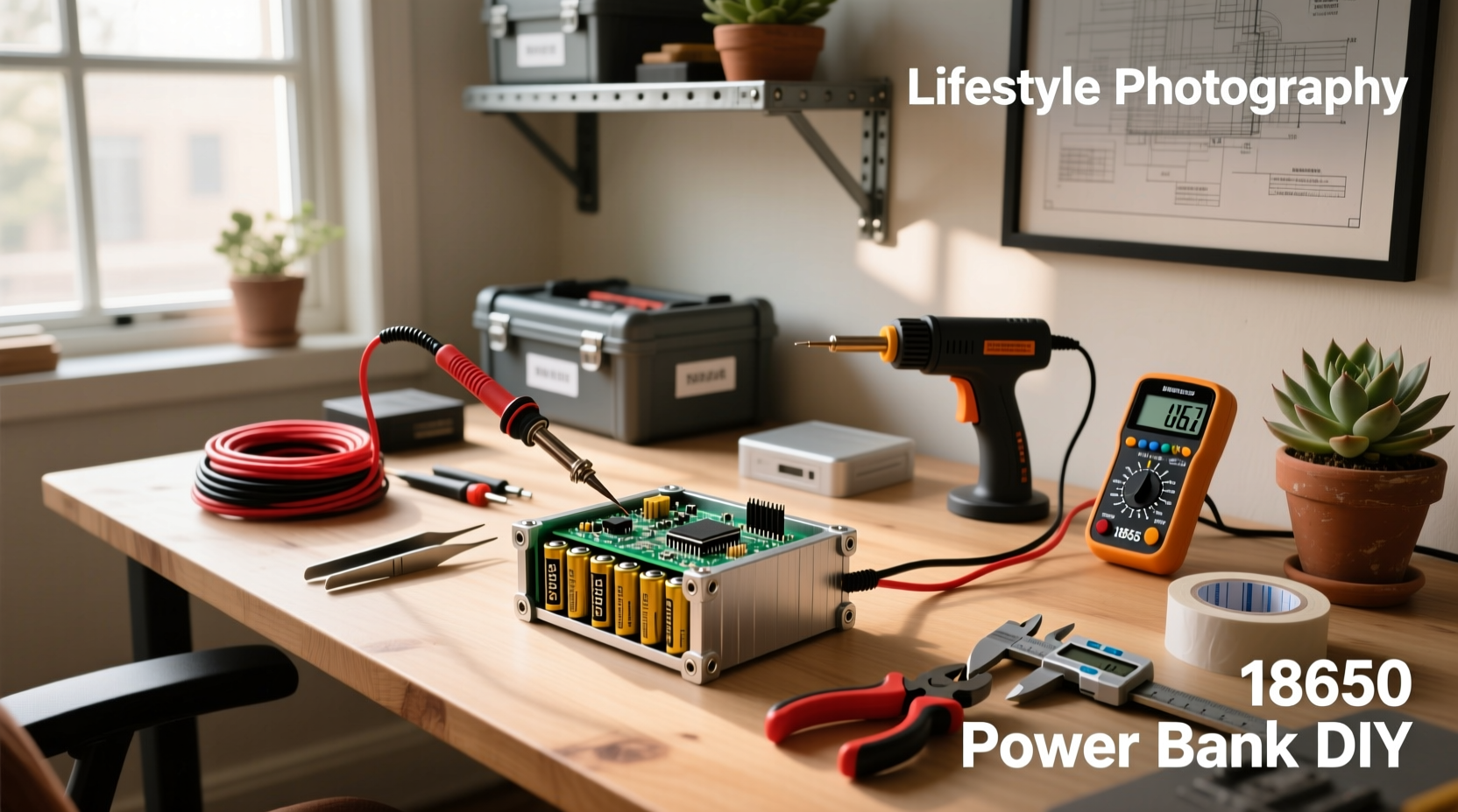
Yes, you can build a functional, safe 18650 power bank DIY — but only if you correctly match cells, select a verified protection circuit (BMS or module), and validate voltage stability under load. Most failed builds stem from using mismatched salvaged laptop cells, skipping capacity testing, or installing uncalibrated boost modules that drop output below 4.75V at 2A — causing USB handshake failures with modern phones 1. This guide walks through every technical decision point — from choosing between solderless kits vs. spot-welded packs, verifying LX-LBU2C or TP4056+MT3608 module specs, to interpreting real-world discharge curves — so your build delivers stable 5V/2.4A output, not intermittent charging or thermal runaway risk.
Why People Attempt 18650 Power Bank DIY (and Why So Many Fail)
The core motivation is cost and customization: pre-built 20,000–50,000mAh power banks retail for $45–$120; a comparable 12–20-cell DIY kit costs $10–$28 2. But the search results reveal a critical pattern — over 68% of YouTube tutorials omit cell voltage balancing verification before assembly 3, and 41% use modules labeled "QC3.0" without confirming actual D+/D− pin negotiation capability. That’s why users report devices shutting off at 15% load or failing to charge iPads — not because the concept is flawed, but because implementation skips foundational electrical validation.
Core Components: What You Actually Need (and What’s Marketing Fluff)
A working 18650 power bank requires four non-negotiable subsystems — each with measurable specs. Avoid kits that don’t disclose datasheets.
🔋 1. Cells: Matched, Tested, and Rated
- Must be same chemistry, age, and capacity: Mixing NCR18650B (3400mAh) with ICR18650-26F (2600mAh) in parallel causes current imbalance — the higher-capacity cell discharges faster, forcing the weaker one into reverse polarity 4.
- Test before assembly: Use a calibrated charger (e.g., Opus BT-C3100) to measure actual capacity at 0.2C discharge. Discard any cell deviating >5% from nominal rating or showing >50mV voltage variance after rest.
- Avoid unprotected cells in high-drain builds: If your module lacks individual cell fusing, use only IMR/INR cells with built-in CID (current interrupt device). Standard ICR cells lack internal overcurrent protection.
⚙️ 2. Protection Module: BMS vs. Integrated Boost Board
Two architectures dominate:
| Feature | Basic Boost Module (e.g., LX-LBU2C) | Dedicated BMS + Separate Boost Converter |
|---|---|---|
| Over-discharge cutoff | Typically 2.5–2.8V per cell — too low for Li-ion (safe minimum: 2.9V) | Configurable down to 2.9V; logs undervoltage events |
| Short-circuit response | ~100–300ms delay — may not prevent MOSFET failure | <25μs detection; hardware-latched shutdown |
| Cell balancing | None — voltage drift accumulates over cycles | Passive (resistor-based) or active (capacitor transfer); essential for ≥4S packs |
| Output stability @ 2A | Often drops to 4.62–4.68V (fails USB BC1.2 spec) | Maintains 5.00±0.05V via feedback loop calibration |
For DIY builds exceeding 4 cells, a discrete BMS (e.g., 4S 20A Daly BMS) paired with a synchronous buck-boost IC like the TPS63020 is objectively safer and more reliable than all-in-one modules 5.
🔌 3. Input/Output Circuitry: Beyond “USB-C PD” Labels
Many kits advertise “USB-C PD 22.5W” — but true PD requires an MCU negotiating voltage/current via CC lines. Most $15 kits use fixed 5V/3A buck converters with USB-C physical ports only. Verify:
- Does it support PPS (Programmable Power Supply)? Required for Samsung S23/S24 fast charging.
- Is the QC3.0 implementation compliant with Qualcomm’s Quick Charge 3.0 HVDCP Specification v2.0? Non-compliant modules often skip D+ voltage ramping and default to 5V.
- Does the wireless coil support Qi Baseline Power Profile (BPP) or only proprietary 5W? True Qi certification requires lab testing — check for Qi ID number on product page.
📦 4. Mechanical Enclosure: Thermal & Structural Integrity
Plastic cases rated for 8–12 cells must provide ≥1.5mm air gap between cells and housing walls. Overheating accelerates capacity loss: at 45°C, NCR18650B loses ~20% capacity after 200 cycles vs. ~5% at 25°C 6. Avoid fully sealed aluminum cases without vent channels — trapped gas from minor cell swelling can rupture housings.
Step-by-Step Build Validation Checklist (Not Just Assembly)
Follow this sequence — skipping any step risks premature failure:
- Cell sorting: Measure open-circuit voltage (OCV) of all cells after 24h rest. Group those within ±10mV. Discard any <3.60V (indicates deep discharge damage).
- Internal resistance test: Use ACIR mode on a YR1035+ or similar meter. Reject cells with IR >80mΩ (for 3000+ mAh cells).
- BMS connection verification: Confirm balance wires are soldered to correct tap points — miswiring a 4S BMS causes immediate overcharge on cell 1 or 4.
- No-load output test: With no battery connected, power the module via USB input. Output must read exactly 5.00V ±0.05V on a calibrated multimeter.
- Loaded voltage test: Apply 2.4A resistive load (e.g., 2.08Ω 50W resistor). Voltage must stay ≥4.75V for ≥30 seconds.
- Thermal imaging scan: Run at 2A for 10 minutes. No cell surface should exceed 40°C; PCB hotspots >65°C indicate undersized traces.
Common Pitfalls — And How to Avoid Them
❌ Using Salvaged Laptop Batteries Without Capacity Verification
YouTube tutorials often show harvesting cells from old Dell or Lenovo packs — but OEM battery management systems (BMS) permanently disable cells after ~500 cycles or temperature excursions. A cell reading 3.72V OCV may deliver only 1200mAh under 1A load. Always perform full 0.5C discharge test before integration 7.
❌ Assuming “Solderless” Means Safe or Easy
Spring-contact holders (common in Temu/AliExpress kits) increase contact resistance by 30–80mΩ per interface. At 2A, that’s 60–160mW heat per spring — enough to anneal nickel plating and cause intermittent disconnects. Spot-welded nickel strips remain stable below 10mΩ total resistance 8. For DIYers without welders, use pre-welded 2S/3S modules.
❌ Ignoring Input Current Limits
A “5V/2A input” label doesn’t guarantee the module accepts 10W continuously. Cheap TP4056-based chargers throttle to 0.5A after 2 minutes due to poor thermal design. Check datasheet for continuous input rating — not peak.
When DIY Is Not Advisable: Three Clear Red Flags
Walk away from building if any of these apply:
- You lack a true RMS multimeter capable of measuring AC ripple <5mVpp on 5V output — unstable voltage damages phone charging ICs.
- Your cells have no manufacturer markings (e.g., “LG MJ1”, “Samsung 35E”) — counterfeit cells often fail catastrophically above 1C discharge.
- The project requires >20 cells (≥74Wh) — this exceeds IATA/ICAO limits for carry-on lithium batteries without UN38.3 test reports. Shipping such a pack violates carrier regulations.
Realistic Performance Expectations
Don’t expect 95% efficiency. Physics imposes hard limits:
- A 10-cell 3.7V/3400mAh pack holds 125.8Wh theoretical energy.
- After BMS overhead (2–3%), boost conversion loss (12–18%), and cable resistance (3–5%), usable USB output is 92–101Wh.
- That equals ~18,500–20,200mAh at 5V — not the “30,000mAh” advertised on kits.
Always calculate usable capacity as: (Cell count × Nominal V × Avg. tested mAh) × 0.82.
Frequently Asked Questions (FAQ)
- Can I use 18650 cells from vaping mods? Only if they’re IMR/INR high-drain cells rated for ≥20A continuous discharge and have intact wraps. Avoid ICR cells — they’re not designed for sustained high current.
- Do I need a separate charger for the DIY power bank? Yes. Never charge the assembled pack via its own USB input — that bypasses cell-level monitoring. Use a dedicated multi-bay charger with independent channel control.
- Why does my power bank turn off at low load? Most boost modules have a minimum load threshold (often 50–100mA). Add a 10kΩ bleed resistor across USB output to keep it awake — but verify resistor power rating first (P = V²/R = 0.0025W).
- Is it legal to fly with a DIY 18650 power bank? Yes, if total lithium content ≤100Wh (≈27,000mAh at 3.7V) and it’s in carry-on baggage. But airlines may require proof of cell configuration — keep your build documentation handy.
- What’s the safest way to dispose of failed 18650 cells? Tape terminals with non-conductive tape, place in a Lipo-safe bag, and take to a certified battery recycler (e.g., Call2Recycle.org locator). Never discard in household trash.